Manufacturing Tolerances for Standard Steel Doors & Frames
SDI 117-23
View PDF
Table of Contents
- Introduction
- Reference Documents
- Notes
- Materials and Finishes
- Frame Tolerances
- Door Tolerances
- Hardware Preparations
- Frame Installation
1. Introduction
It is the intent of this publication to provide users with definitive information regarding manufacturing tolerances of standard steel doors and frames. This document is not to be referenced for manufacturing tolerances of specialty products, i.e., bullet, acoustical, windstorm. This document is intended for in-plant inspections. It may be used as a reference document for on-site inspections where there is no evidence of damage to material or improper installation.
The information contained herein pertains to doors and frames manufactured in accordance with ANSI/SDI A250.8 Specifications for Standard Steel Doors and Frames. It is not intended to be a reference for specialty doors or unusual door and frame conditions.
2. Reference Documents:
- ANSI/SDI A250.8-2017 SDI 100 Specifications for Standard Steel Doors & Frames
- ANSI/SDI A250.6-2020 Recommended Practice for Hardware Reinforcings on Standard Steel Doors and Frames
- ANSI/SDI A250.3 Test Procedure & Acceptance Criteria for Factory Applied Finish Coatings for Steel Doors & Frames
- ANSI/SDI A250.10-2020 Test Procedure & Acceptance Criteria for Prime Painted Steel Surfaces for Steel Doors & Frames
- ANSI/SDI A250.11-2022 Recommended Erection Instructions for Steel Frames
- ANSI/BHMA A115 Specifications for Steel Door and Frame Preparation for Hardware (A115.1 – A115.18)
- ASTM A568-2019 Standard Specification for Steel, Sheet, Carbon, Structural, and High-Strength, Low-Alloy, Hot- Rolled and Cold-Rolled, General Requirements for
- ASTM A653-2018 Standard Specification for Steel Sheet, Zinc-Coated (Galvanized) or Zinc-Iron Alloy-Coated (Galvannealed) by the Hot-Dip Process
- ASTM A924-2022 Standard Specification for General Requirements for Steel Sheet, Metallic-Coated by the Hot-Dip Process
- NFPA 80 Standard for Fire Doors and Other Opening Protectives, 2022 Edition
- SDI 122-2021 Installation and Troubleshooting Guide for Standard Steel Doors and Frames
- SDI 134-2020 Glossary of Terms for Hollow Metal Doors and Frames
3. Notes
3.1 Tolerances
All values which do not carry specific tolerances or are not marked maximum or minimum shall have the following tolerances: Linear dimensions shall be ± 1/16 in. (1.6 mm). Weight or force shall be ± 2%. Angles shall be ± 2 degrees. Where only minus tolerances are given, the dimensions are permitted to be exceeded at the option of the manufacturers.
3.2 Gauge vs. Thickness
While the term ‘gauge’ is no longer common for defining material thickness it is still used to specify doors and frames for ordering purposes. The term ‘thickness’ is used when defining the actual dimension of an item, and the term ‘gauge’ is used in the context of specifying a particular door or frame.
3.3 Metric
Values stated without parenthesis are the requirement. Values in the parenthesis are explanatory or approximate information.
4. Materials and Finishes
4.1 Steel Thickness
Manufacturers no longer order sheet and coil to a specific gauge, but rather to a minimum decimal thickness. This thickness is the lowest of the range for a specific gauge. The steel supplier is therefore permitted to exceed, but not be less than the specified decimal thickness. These minimum values meet the stringent requirements of test facilities and labeling agencies
such as UL Solutions, and ITS/Intertek Testing/Warnock Hersey. Examples of minimum allowable steel thickness:
| Gauge (MSG) | Minimum |
| 20 | 0.032˝ |
| 18 | 0.042˝ |
| 16 | 0.053˝ |
| 14 | 0.067˝ |
| 12 | 0.093˝ |
| 10 | 0.123˝ |
| 7 | 0.167˝ |
Gauge (MSG) are for reference purposes only.
4.2 Steel Coatings
Thickness of metallic coatings (generally zinc) are defined by ASTM A924, Standard Specification for General Requirements for Steel Sheet, Metallic-Coated by the Hot-Dip Process and A653, Standard Specification for Steel Sheet, Zinc-Coated (Galvanized) or Zinc-Iron Alloy-Coated (Galvannealed) by the Hot-Dip Process. The two most commonly used designations are A40 and A60. Minimum requirements for these designations are:
A40 = 0.40 oz/ft2 total both sides.
A60 = 0.60 oz/ft2 total both sides.
For reference, 1 oz/ft2 = 1.7 mils thickness.
4.3 Factory Applied Coatings
Factory applied coatings (primer, finish paint, etc.) are subject to performance standards rather than thickness, the dry film thickness is irrelevant. Such coatings must comply with performance criteria of:
ANSI/SDI A250.3 – Test Procedure and Acceptance Criteria for Factory Applied Finished Coatings for Steel Doors and Frames
OR
ANSI/SDI A250.10 – Test Procedure and Acceptance Criteria for Prime Painted Steel Surfaces for Steel Doors and Frames.
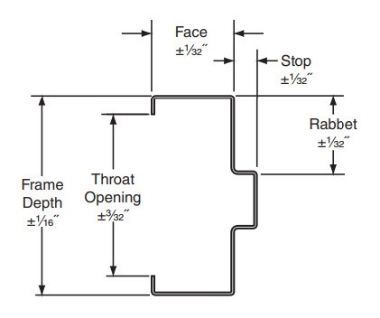
5. Frame Tolerances
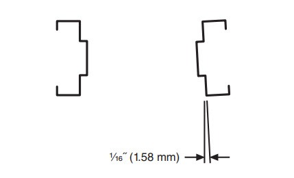
5.1 Frame Cross Section Profile
Permissible tolerances in frame profile surfaces are as shown in Figure A:
Figure A – Profile Tolerances
5.2 Frame Opening & Vertical Locations
Figure B – Opening Tolerances
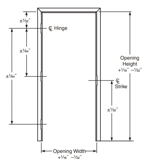
5.3 Bow or Twist of Jambs or Header
Realizing that frames are somewhat “pliable”, and require bracing and alignment during installation, allowable deformation (bow, twist, etc.) of jambs or header of frame prior to installation shall not result in a reduction of opening sizes more than 1/16˝ beyond those shown in Figure “B” when measured at any point.
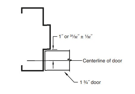
5.4 Horizontal Alignment of Door Within Rabbet
Hinge and strike backsets shall allow the horizontal centerline of the door to be in line with the horizontal centerline of the frame rabbet ± 1/32˝ prior to installation. Figure “C” is an example based on a 1 3/4˝ door in a 1 15/16˝ rabbet.
Figure C – Horizontal Alignment
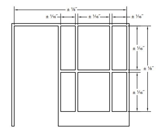
5.5 Frames with Lights or Panels
Opening sizes (width or height) for side lights or transom lights or panels and for borrowed light frames shall be subject to a tolerance of ± 1/16˝ for each individual light or panel. These tolerances shall be non-accumulative so that the overall frame opening sizes are not increased by more than 1/8˝. (Reference Figure D.)
Figure D – Frames with Lights or Panels
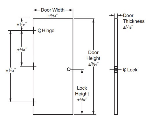
6. Door Tolerances
6.1 Door Size, Thickness, and Vertical Locations
Figure E – Doors
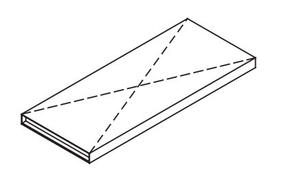
6.2 Door Squareness
When measured diagonally from corner to corner along the same face, the measurements shall be within 1/16˝ of each other. (Reference Figure F.)
Figure F – Squareness
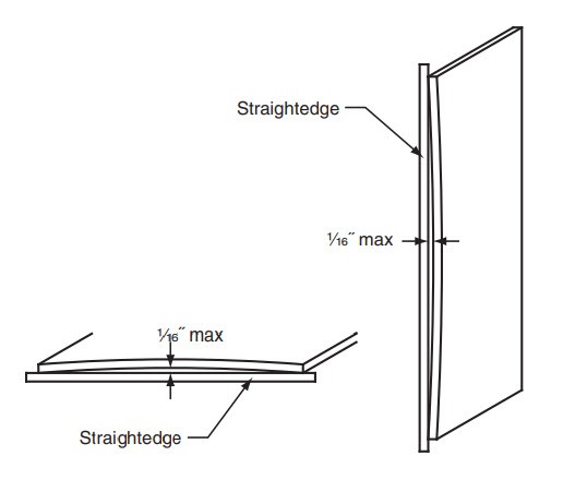
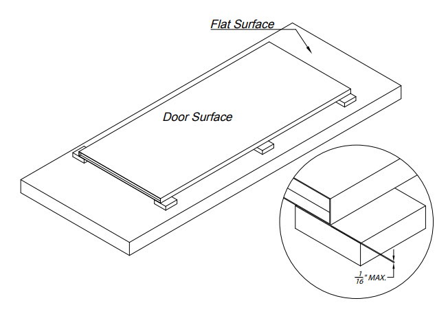
6.3 Door Perimeter Flatness
Using a straightedge suitable for the size of the door, the straightedge is laid against the door face at or within 1/4˝ of the top, bottom, hinge edge, and lock edge on both faces any deviation between the face and the straightedge shall not allow a 0.0625˝ rod or block to pass. (Reference Figure G)
Note: The straightedge shall be allowed to “rest” naturally on the door surface, not pulled down at one end to meet the door.
Figure G – Flatness
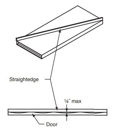
6.4 Door Face Bow or Crown (Flatness)
When a straightedge suitable for door size is laid diagonally against the door face at least 1/2˝ from corners any deviation between the face and the straightedge shall not allow a 0.125″ rod or block to pass.
Note: The straightedge shall be allowed to “rest” naturally on the door surface, not pulled down at one end to meet the door. (Reference Figure H)
Figure H – Flatness
6.5 Door Twist
The door is laid on a suitable, flat fixture or surface that is free of any warp, bow, or twist. Support blocks of identical heights shall be inserted between the fixture and the door face at all four corners of the door. Any deviation between the face and the support blocks shall not allow a 0.0625˝ rod or block to pass. An additional two blocks shall be inserted between fixture or surface and the door face at or near
mid points of door height.
Note: The door shall be allowed to “rest” naturally on the support blocks, not pulled down at any corner to meet the blocks. (Reference Figure I)
Figure I – Door Twist
6.6 Doors with Lights or Panels
Opening sizes (width or height) for lights or panels cut into doors shall be subject to a tolerance of ± 1/16˝ for each individual light or panel.
7. Hardware Preparations
7.1 Vertical Locations
Tolerances for vertical locations are as noted in Paragraphs 5.2 and 6.1.
7.2 Horizontal Alignment
Tolerances for horizontal alignment of door and rabbet are as noted in Paragraph 5.4.
7.3 Mortise Depth
The depth of hardware items mortised into edges of doors (such as hinges, strikes, lock fronts, flushbolts) shall be as defined on manufacturer’s templates and/ or ANSI A156.115 documents subject to an additional tolerance of ± 1/64˝.
7.3.1 Cutout Depth at Frame or Door Faces
To allow for field adjustments, typically accomplished by shimming, hardware cutouts (such as hinges) that extend from door edges around to faces or from frame rabbet around to faces are allowed to exceed mortise depth by 1/16˝.
7.3.2 Depth for Recessed or Concealed Hardware
The depth for hardware items recessed into top or bottom of doors or edges of doors (such as pocket pivots, floor closers, top pivots, concealed closers or holders, etc.) shall be as defined on manufacturer’s templates subject to an additional tolerance of +1/16˝ –0˝. Notches in door faces shall have similar tolerances.
8. Frame Installation
8.1 Frame Installation Tolerances
While this document is mainly concerned with tolerances relating to the manufacturing process, openings will not function properly if the frame is not installed within recognized tolerances.
Figures “J-K-L-M” show examples of the accuracy to be maintained while setting and installing frames. Instructions for installation may be found in ANSI/SDI A250.11.
Figure J – Squareness
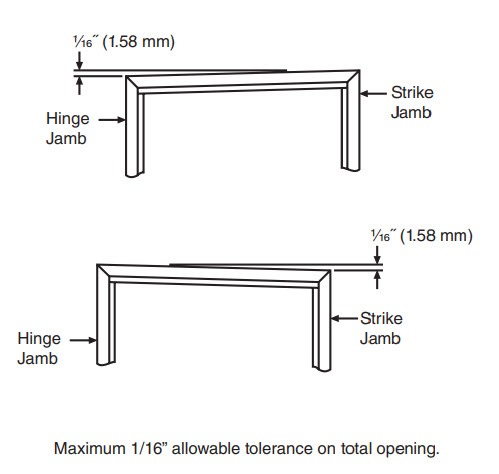
Figure K – Plumbness
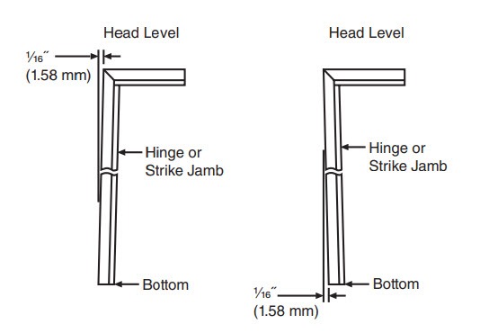
Figure L – Alignment
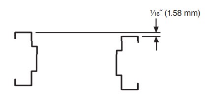
Figure M – Twist
8.2 Troubleshooting
Further information regarding corrective actions for door & frame openings may be found in SDI-122.